
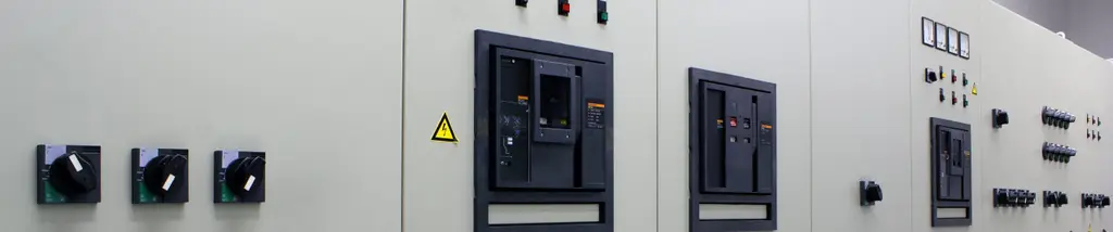
In this article, we will discuss how trapped key interlocking is implemented within switchgear control whilst maintaining system integrity. Factors such as aging infrastructure, technological advancements, lack of investment, demands for cleaner and reliable ever-present energy, have significantly altered the scenery of the energy sector with switchgear systems becoming increasingly complex. Switchgear systems can utilise or involve several incomers, earthing systems, making the integration of HV (High Voltage), MV (Medium Voltage), LV (Low Voltage) or switching incomers and common supply busbars potentially complicated. This not only increases the potential level of complexity but also the need for robust and reliable safety systems to ensure personnel safety, electrical equipment protection and its correct, safe mode of operation at all time. The safe and effective operation of switchgear can be achieved through a sequential release system whichsets out a process that must be followed removing the need for reliance on work instructions alone. The system designer should consider the operational processes in conjunction with the safe state of equipment. A challenge with switchgear if one or more supplies shuts down due to an overload or power failure or for planned maintenance purposes is that the remaining supplies will have to carry the load. Therefore, the sequence of operation must be controlled in such a way to ensure that power is maintained, the shutting down of the remaining supplies due to overload is avoided and the collapse of the entire system is prevented. 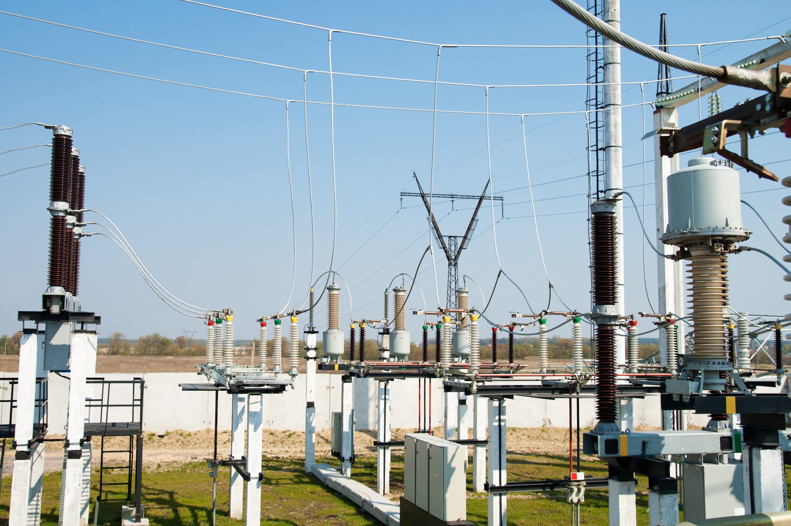 Trapped key interlocking constitutes an effective way to control the sequential operation of switchgear systems. A trapped key interlocking system can ensure a process is followed and cannot be circumvented. The transfer of a key ensures that wherever personnel find themselves, in either starting or shutting down operations, they can be assured that they are safe through the control of switchgear isolation. Management of complex switchgear systems can be controlled through a blanking system. The blanking system means that some of the symbols on the busbar locks have a part coded lock which denotes it can be isolated by more than one of the keys forming the switchgear system. For instance, if we part coded a lock to A ‘Blank’ we can use any 2-character symbol keys with a prefix of ‘A’ to operate the lock (see below for more examples). The system’s integrity is maintained by the design of the nomenclature chosen for the incomer and busbars. This means the open and closing operation of the switchgear can be controlled with less locks and keys. Blanking systems, although not suitable for every switchgear application, offer some significant advantages. More specifically, they remove the need for excess keys and additional key exchange boxes allowing for a simpler interlocking system. Implemented correctly, they can also provide cost and time saving benefits.
Applications
Applications for incomer and busbar interlocking or incomer, generator and busbar interlocking are used in any environment where there is a demand for reliable energy sources such as data centres or building management services like factories, hospitals, airports, rail and stadiums.
Example 1: Incomer and Busbar Interlocking
This system requires five locks and three keys. In the normal operation the keys are trapped in the incomers in the closed position and both bus couplers are open. The symbol sequence will allow appropriate incomers to be open allowing the key to be released, transferred and inserted and trapped to the associated bus coupler allowing it to be closed. The symbols used here are AA, AB and BB for the Incomers and A_ (A BLANK) and _B (BLANK B) for the bus couplers.
Example 2: Incomer and Busbar Interlocking
This system will require four locks and two keys. The keys are trapped in incomer 1 and 2 with the switches in the closed position. Both the bus coupler and incomer 3 open. The symbol sequence will only allow incomer 3 or the bus coupler to be closed after the appropriate key has been released, transferred and inserted into the bus coupler or incomer three lock. The system ensures that only two incomers are supplying at any time. The symbols used here are AA and AB for the incomers and A_ (A BLANK) for the bus coupler.
Example 3: Incomer, Generator and Busbar Interlocking
The normal operation is the two incomers are closed with bus coupler and generator are both open. The symbol arrangement using key symbols AA, AB, A_ (A Blank) on locks with just keys AA AB will ensure safe switching operation. It will not be possible to have incomer 2 and generator closed at the same time to avoid paralleling. The symbols used here are AA and AB for the incomers and A_ (A BLANK) for the bus coupler.
Designing an interlocking system
The design of an interlocking system is a process that must be carefully undertaken. A good interlocking scheme requires all risks and operational procedures are considered in advance ensuring integrity. This can proactively address how the system will respond in both operational and failure modes along with routine maintenance. An interlocking system will set out the process and steps that must be followed to ensure personnel cannot access potentially dangerous areas. When maintenance activities are being performed, trapped key interlocking systems can ensure that the switchgear system is always put in a safe state. Trapped key also ensures that the system operates efficiently and there is no chance of, for example, switching two incoming feeds on to a common busbar significantly reducing risks (such as fire, arc flash) as well as the possibility of equipment damage.
Conclusion
Complicated switchgear systems need to have a robust management system to protect personal and machinery. Designed correctly, an interlocking scheme can contribute to eliminating human error on site while permitting safe access to electrical equipment. Integration of older equipment with new switchgear can be a challenge, trapped key interlocking allows for the safe integrating with OEM switchgear, ensuring safe site operations and negating the need for complicated controls.
Castell have been delivering safety solutions for switchgear since 1922. Working closely with original equipment manufacturers (OEMs) has enabled Castell to produce interlocks designed specifically for use on the leading manufacturers own breakers, isolators, disconnectors and earth mechanisms. Castell offer a range of isolation products for switchgear applications. The FS lock range can perform in the harshest environments using figure symbols as the unique identifiers enables defining a unique blanking system which allows for easier use of switchgear within the integrity of the trapped key system. FS locks can be incorporated into all Castell product for isolation equipment. Where isolation requires an un–masterable solution on switchgear, Castell Q range offers the ability to uniquely code locks to site requirements and as with the FS range, the Q range of locks can be used on all Castell isolation products.
To discuss any switchgear application requirements please contact our team of technical experts: [email protected]